| Description |
|
Radial piston arrangement, with 5 or 7 pumping elements each per pump section. External mounting type. Face mounting, Valve controlled, Fixed delivery. Bi-directional rotation of shaft. Available with extension shaft for through drive. With extension bracket assembly for coupling a low pressure pump having standard flange. Flows can be combined internally, externally to feed one circuit or used independently to feed Two circuits. |
![]() |
| Section |
| Unit Dimensions |

| Technical Specifications |
| Designation ........................... | 
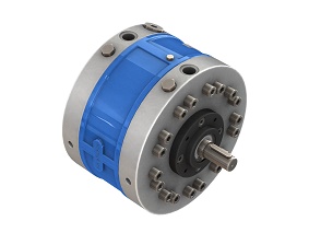
12RC basic radial piston pump group. |
| Design .................................. | Radial piston, valve controlled. |
| No. of pistons ........................ | 5 or 7; depending upon flow requirement. |
| Mounting ............................... | Face mounting. |
| Interface ................................ | Factory standard. |
| Direction of rotation ........... 12RC | Can be run in either direction. |
12RCE ...................................... |
Depends upon the direction of rotation of pump attached. |
| Connection ................ Suction |
G 3/4 female.
Suction head -- The oil level can be max. 300 mm below the suction port of the pump. Suction pipe size -- 30 o. d. x 2 th. (as far as possible use straight pipe) |
Delivery .................................. |
G 1/2 female. |
| Suction pressure ............................ | 0.02 to 3 bar positive. |
| Speed range .......................... | 1000 to 2000 rpm. |
| Hydraulic medium .................. | Mineral oil. |
| Viscosity range ...................... | 10 to 100 cSt. |
| Optimum Viscosity range ....... | 16 to 32 cSt. |
| Temperature range ................ |
-10 °C to +80 °C. (Do
not exceed viscosity limits at extreme temperatures for efficient running of the pump) |
| Fluid cleanliness requirement .. | As per ISO Code 16/13. |
| Performance .......................... | Refer Table No. 1. |
| Mass .................................... | 30 kg. |
Table No. 1
Code No. |
Geometrical displacement CC / REV |
Rated output at 1450 rpm |
Rated output at 1450 rpm & 95% efficiency |
Operating pressure bar |
Input power requirement (@ 1450 rpm) |
|||||||||||||||||
50 bar |
100 bar | 150 bar | 200 bar | 250 bar | 300 bar | 315 bar | 350 bar | 400 bar | ||||||||||||||
| KW | Hp | KW | Hp | KW | Hp | KW | Hp | KW | Hp | KW | Hp | KW | Hp | KW | Hp | KW | Hp | |||||
5A |
7.7 | 11.2 | 10.6 | 400 |
1 | 1.4 | 2.1 | 2.8 | 3.1 | 4.2 | 4.1 | 5.6 | 5.1 | 7 | 6.2 | 8.4 | 6.5 | 8.8 | 7.2 | 9.8 | 8.2 | 11.1 |
7A |
10.8 | 15.7 | 14.9 | 400 |
1.4 | 2 | 2.9 | 3.9 | 4.3 | 5.9 | 5.8 | 7.8 | 7.2 | 9.8 | 8.7 | 11.8 | 9.1 | 12.3 | 10.1 | 13.7 | 11.5 | 15.7 |
5B |
10.1 | 14.7 | 14 | 315 |
1.4 | 1.8 | 2.7 | 3.7 | 4.1 | 5.5 | 5.4 | 7.3 | 6.8 | 9.2 | 8.1 | 11 | 8.5 | 11.6 | ||||
7B |
14.1 | 20.5 | 19.5 | 315 |
1.9 | 2.6 | 3.8 | 5.1 | 5.7 | 7.7 | 7.5 | 10.2 | 9.4 | 12.8 | 11.3 | 15.4 | 11.9 | 16.1 | ||||
5C |
12.7 | 18.5 | 17.6 | 250 |
1.7 | 2.3 | 3.4 | 4.6 | 5.1 | 6.9 | 6.8 | 9.2 | 8.5 | 11.5 | ||||||||
7C |
17.8 | 25.8 | 24.5 | 250 |
2.4 | 3.2 | 4.7 | 6.4 | 7.5 | 9.7 | 9.5 | 12.9 | 11.9 | 16.1 | ||||||||
Note : For double pumps, the above pump code number needs to be modified in the following manner. The first digit in the code number indicates number of pumping elements in each pump section. The second letter indicates flow and pressure rating of the pumping elements of P1 port end section and the third letter indicates flow and pressure rating of the pump elements of P2 port end section. Code no. 5AC for example, indicates a double pump having a flow and pressure rating of 5A for P1 port end section and 5C rating for P2 port end section.
| Accessories |
Extension
shaft
(For through drive) Dimensions
Note : Torque limitation - The sum of torque used for the
piston
pump and torque used at extended shaft end should not exceed 148
Nm ( 22.2 kW @ 1450 rpm )
|
PRIMING PROCEDURE FOR CLOSED EXECUTION PUMP |
|
| A] When the Casing Pump is mounted Horizontally. | |
|
|
|
| Case I :
When the pump suction port height exceeds 300
mm above oil level.
1) Provide a check valve with almost zero cracking
pressure on the suction pipe. ( Refer check valve
model code given below). Case II: When the pump suction port height is less than 300 mm above oil level. 1) The pump need not have a check valve as mentioned
in Case I. |
|
| B] When the Casing Pump is mounted Vertically | |
|
|
Case I :
When the pump is immersed in oil.
1) Make the connection for air bleeding as shown in fig. using the kit provided with the pump. 2) Loosen the Casing air bleeding plug completely. 3) Wait for some time for the oil to fill the pump casing. 4) The plug may now be tightened. 5) Now run the pump for short period at zero load. 6) Adjust the main pressure relief valve of the system to required value and start using the system. |
|
|
Case II:
When the pump suction port is above oil level.
1) Make the connection for air bleeding as shown in fig. using the kit provided with the pump. 2) Fit a check valve with almost zero cracking pressure at the bottom of the suction pipe. (When suction port height exceeds oil level by 300 mm. ( Refer check valve model codes given below). 3) Now fill the pump casing with oil. This can be done by providing a pipe connection to alternate suction port as shown. 4) Now loosen the casing air bleeding plug completely & fill the casing till oil is seen coming out of casing air bleeding port. 5) Tighten the casing air bleeding plug once the casing is filled. Also, plug the oil filling port & ensure it to be air tight. 6) Now run the pump at zero load for some time. 7) Adjust the main pressure relief valve of the system to required value and start using the system. |
| Note:-- Priming is not required to be done every time you start the pump after short durations (a day or two) of non-operation. | |
| Suction pipe specification | |
| 1) 12RC-series : 30 O.D.x 2 mm thick (Preferably straight) | |
| Check valve model codes ( To be ordered separatly) | |
| 1) 12RC-series : C20T0-03 | |
| Ordering Informations |

Note 1 :
A double pump of model code 12RC5AD, for example, will have 5 pumping elements
of 'A' flow and pressure rating at it's P1 port end section and 5 pumping elements
of 'C' flow and pressure rating at it's P2 port end section.
Note 2 :
For Bell housing assembly Refer Sheet No.
p09035.
For Extension bracket assembly Refer Sheet No. p09090.
| All rights reserved. Subject to revision. |
|
|
|
|
|
Regd. office & Works : |
|
Copyright ©
Polyhydron Pvt. Ltd. Belgaum, India. |
Updated on May 13, 2010 02:30 pm .